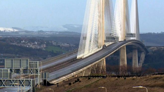
BBC: “Falling ice causes first Queensferry Crossing closure”


Keeping such bridges open, even in icing conditions, is really not rocket science. What, to me anyway, is the obvious solution – to pass an electrical heating current through the bridge’s support cables – doesn’t seem to be “obvious” to other research scientists and engineers whose “Thermal Systems” for melting the ice are reviewed here.
I suggested this simple solution, outlined the calculations required and warned of some dangers in an email to the Queensferry Crossing bridge authorities and contractors in March 2019, but as usual, the authorities ignore solutions until there is a political price to be paid for continuing to ignore solutions in a pig-headed, in-denial kind of way that politicians like to get away with, if they possibly can.
There follows a link to a PDF of the email I sent the bridge authorities last year – hopefully you can click the link and open and / or download the PDF so you can read it.
Queensferry falling ice hazard solution – electrically-heated cable stays
Deicing power for 70km of cables
@ 100W/m = 7MW = household electricity within a 3 mile radius of the bridge.
@ 250W/m = 17.5MW = household electricity within a 5 mile radius of the bridge.
Cable strands
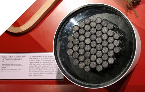

Some strands in the cable are better situated for heating the cable than other strands, depending on their position in the cable as I have labelled them alphabetically, beginning with the label “A” for the centre strand (which is the worst strand for heating the outside of the cable, where the ice would be) and labelling the outer strands last in alphabetical order, which are best for heating the outside of the cable.
The cable strands are by convention named here using the format – “(Number of strands in the cable)-(Letter)”. Thus the centre strand in the 55-strand cable is named as “55-A”, the 6 strands immediately surrounding the sole 55-A are all named of type “55-B”.
For each strand in the cable we can assign a factor of heating capacity, calculated approximately in proportion to the maximum geometric angle in the cross-section plane between 2 radial rays centred on the strand and tangential to the surface of 2 other strands while all of the intermediate radial rays (centred on the strand which cross an arc which subtends the angle) may not pass through any other strand, where a factor of heating capacity of 1 equals an angle of 1/6th of a revolution or 60°.
Colloquially, this factor of heating capacity may be said to be a measure of the angle of “the field of view” of the stay pipe as seen by an observer from the centre of a strand imagining that strand to be transparent while the other strands are opaque.

For the 55-strand cable, the total heating capacity factor assigned is 50.4.
For the 55-strand cable, there are a total of 24 strands which have utility for heating the cable – 6 of the 55-F type name strands, 6 x 55-Gs and 12 x 55-Hs. The 31 other strands (the 55-A to 55-Es) are not needed for heating per se, though could carry electrical currents whether by design or otherwise.
We can tabulate for each strand label, the heating power fraction and percentage, according to each strand’s heating capacity factor as a fraction of the cable’s total heating capacity factor.
| Strands-label | Heating power fraction | Heating power % |
|---|---|---|
| 55-F | 1/50.4 | 2.0% |
| 55-G | 2/50.4 | 4.0% |
| 55-H | 2.7/50.4 | 5.4% |
VSL SSI 2000 Stay Cable System

The stay cable system for the Queensferry Crossing was provided by a company called “VSL” and their brochures identify certain “main dimensions” and numbers of strands which correspond to the number of strand attachment shafts in each of VSL’s range of stay cable anchor heads.

As I did above for the 55 strands case, I detail below similar strand heating capacity calculations for each of the other “main dimension” number of strands used in the Queensferry Crossing – 61, 73, 85, 91 and 109 strands, but not for 43 or 127 strands which size of anchor heads weren’t used.


For the 61-strand cable, the total heating capacity factor assigned is 54.
For the 61-strand cable, there are a total of 24 strands which have utility for heating the cable – 6 x 61-Gs, 12 x 61-Hs and 6 x 61-Is. There are 37 other strands – the 61-A to 61-Fs.
| Strands-label | Heating power fraction | Heating power % |
|---|---|---|
| 61-G | 2/54 | 3.7% |
| 61-H | 2/54 | 3.7% |
| 61-I | 3/54 | 5.6% |


For the 73-strand cable, the total heating capacity factor assigned is 58.8.
For the 73-strand cable, there are a total of 30 strands which have utility for heating the cable – 12 x 73-Hs, 6 x 73-Is and 12 x 73-Js. There are 43 other strands – the 73-A to 73-Gs.
| Strands-label | Heating power fraction | Heating power % |
|---|---|---|
| 73-H | 1/58.8 | 1.7% |
| 73-I | 2.4/58.8 | 4.1% |
| 73-J | 2.7/58.8 | 4.6% |


For the 85-strand cable, the total heating capacity factor is 62.4.
For the 85-strand cable, there are a total of 30 strands which have utility for heating the cable – 6 x 85-Is, 12 x 85-Js and 12 x 85-Ks. There are 55 other strands – the 85-A to 85-Hs.
| Strands-label | Heating power fraction | Heating power % |
|---|---|---|
| 85-I | 1/62.4 | 1.6% |
| 85-J | 2/62.4 | 3.2% |
| 85-K | 2.7/62.4 | 4.3% |


For the 91-strand cable, the total heating capacity factor is 66.
For the 91-strand cable, there are a total of 30 strands which have utility for heating the cable – 12 x 91-Js, 12 x 91-Ks and 6 x 91-Ls. There are 61 other strands – the 91-A to 91-Is.
| Strands-label | Heating power fraction | Heating power % |
|---|---|---|
| 91-J | 2/66 | 3% |
| 91-K | 2/66 | 3% |
| 91-L | 3/66 | 4.5% |


For the 109-strand cable, the total heating capacity factor is 70.8.
For the 109-strand cable, there are a total of 36 strands which have utility for heating the cable – 12 x 109-Ks, 6 x 10⁹-Ls, 6 x 10⁹-Ms and 12 x 109-Ns. There are 73 other strands – the 109-A to 109-Js.
| Strands-label | Heating power fraction | Heating power % |
|---|---|---|
| 109-K | 1/70.8 | 1.4% |
| 109-L | 2.4/70.8 | 3.4% |
| 109-M | 2/70.8 | 2.8% |
| 109-N | 2.7/70.8 | 3.8% |

109-strand cable anchor
For now, I am assuming for simplicity that the nominal maximum heating power in Watts/metre of cable length is the same as the stay pipe diameter in mm.
| Number of strands in the cable |
Stay Pipe Diameter (mm) |
Heating power (Watts/metre) |
|---|---|---|
| 55 | 200 | 200 |
| 61 | 225 | 225 |
| 73 | 250 | 250 |
| 85 | 250 | 250 |
| 91 | 280 | 280 |
| 109 | 315 | 315 |
 This is not far off the maximum heat radiation from the sun on such a stay pipe, square on to the sun, at midday, midsummer, on a cloudless day – or more than enough heat to melt any ice in short order!
At this maximum heating power and after the cable cores warm up, they will emit 1000÷π = 318 Watts of heat energy per metre-squared of stay pipe surface area.
Strands Power, Current and Voltage per Metre
It is now possible to tabulate for each “main dimension” cable-label strand, the maximum heating power per metre and assuming a strand resistance of 0.001137 ohms per metre, what the maximum strand current and voltage potential per metre would be.
| Strands-label | Maximum strand power (Watts/metre) | Maximum strand current (Amps) | Maximum strand voltage (milliVolts/metre) |
|---|---|---|---|
| 55-F | 4.0 | 59 | 67 |
| 55-G | 7.9 | 84 | 95 |
| 55-H | 10.7 | 97 | 110 |
| 61-G | 8.3 | 86 | 97 |
| 61-H | 8.3 | 86 | 97 |
| 61-I | 12.5 | 105 | 119 |
| 73-H | 4.3 | 61 | 70 |
| 73-I | 10.2 | 95 | 108 |
| 73-J | 11.5 | 100 | 114 |
| Strands-label | Maximum strand power (Watts/metre) | Maximum strand current (Amps) | Maximum strand voltage (milliVolts/metre) |
| 85-I | 4 | 59 | 67 |
| 85-J | 8 | 84 | 95 |
| 85-K | 10.8 | 98 | 111 |
| 91-J | 8.5 | 86 | 98 |
| 91-K | 8.5 | 86 | 98 |
| 91-L | 12.7 | 106 | 120 |
| 109-K | 4.4 | 63 | 71 |
| 109-L | 10.7 | 97 | 110 |
| 109-M | 8.9 | 88 | 101 |
| 109-N | 12.0 | 103 | 117 |
Cable voltages and power
To calculate the cable voltages and power and to calculate the total maximum power to heat all the cables of the Queensferry Crossing accurately, I needed to know how many of each size of cable and their lengths.
UPDATE:
In April 2021, Transport Scotland finally released to me the details of the lengths, the number of strands and the stay pipe details for each stay cable of the Queensferry Crossing. To handle all the electrical-heating calculations for all this data, I wrote a spreadsheet – the details and download for which can be found in my new blog post:
Bridge Stay Cable Electrical-Heating Strand Calculator

Anchor head vacant strand shafts
The released cable data revealed that the Queensferry Crossing designers have freely used intermediate numbers of strands in the stay cables, leaving some of the anchor heads’ strand attachment shafts vacant.
| Number of strand shaft vacancies in anchor head | Number of cables with such anchor heads |
|---|---|
| 0 | 30 |
| 1 | 28 |
| 2 or more | 230 |
Vacant strand shafts may be considered for use to occupy with additional signal-only strands for the cable, or alternate heating-only strands if those vacant strand shafts are located on the periphery of the cable, near to the stay pipe.
(“-only” in this context meaning “not load bearing” so such additional strands could be thinner or made of optical fibre for signals, copper to maximise the current-carrying capacity through the shafts and/or aluminium to reduce the weight of the strand but anodised aluminium to increase emissivity and/or some other alloy for its electrical heating properties.)
HDPE Sheathed Stay Cable Strands
Other than at the anchorages where it is stripped off so the wedges can grip onto the wires, the strands are protected by an HDPE sheath with good electrical insulator properties – more than enough to insulate the cable heating voltages required – a maximum of about 100V for the longest cables.

No Cathodic Hydrogen Charging
The integrity of the HDPE sheath prevents a corrosion process whereby moisture from the outside air could in theory penetrate any wear-and-tear gaps in the strand’s HDPE sheath to react slowly with the zinc galvanic coating to liberate hydrogen atoms from the water which could threaten to embrittle the steel wires over time with the potential eventually to lead to broken wires.
Likewise, the same integrity of the HDPE sheath would also prevent any possibility of the establishment of a cathodic hydrogen charging circuit through non-existing electrolyte-infiltrated gaps in the sheath. So in normal operation, the heating voltages and currents would be unable to emit hydrogen within the sheath – for the same reason that domestic electrical power cables do not emit hydrogen within their insulating sheaths either.
However, should there ever be a failure of the HDPE sheath integrity and consequential ingress of damp, salty air (or any other electrolyte) which establishes a new fault or leakage circuit then the heating system’s fault or leakage current detection circuits must be able to detect the fault condition, immediately cut the power to avoid any risk of exacerbating mechanisms of hydrogen emission and embrittlement and report the fault condition so as to prompt remedial maintenance, of course. (See “DC Circuit Diagrams”)
Temperature of the cable strands when heating

I’ve calculated the expected temperature of the heating strand’s HDPE sheaths as a function of the heating power in Watts per square metre of stay pipe surface.
The void between the outer heating strands and the inner face of the stay pipe requires the strands to cool by radiation, which may be calculated using the Stefan–Boltzmann law. The smaller void with the compact arrangement of strands cools the strands and heats the stay pipe a bit better. The conduction of heat energy from the inner face to the outer face of the stay pipe is relatively efficient and therefore relatively insignificant to the strand sheath temperature but may be calculated simultaneously using Fourier’s Law of thermal conduction.
HDPE copes with boiling temperatures quite well so the strand sheaths ought to cope very well with a temperature of under 70°C at the assumed maximum heating power of 318 W/m². Cognisance of the commensurate sheath temperature would inform design selection of a system’s actual maximum heating power.
Should the strand temperature rise sufficiently to melt the wax coating then the melted wax would still be constrained to flow within the HDPE sheath and so flow rates may be negligible.
The above calculation of temperature assumes that the stay pipe surface is being cooled to 0°C, by melting snow or ice or by sleet. Temperature sensors must inform the heating system’s computer control to reduce the heating power appropriately when the temperature of the stay pipe surface rises above 0°C.

Forced Convection
Other bridges subjected to much icier weather may require more powerful heating so strand overheating may be a greater risk and then in order to enhance the heat transfer from strands to stay pipe, one could force convection in the air space between the strands and stay pipe, by oscillating an air flow up and down the cable and creating air turbulence within the pipe.
I don’t propose to spend any time soon researching exactly how forced convection could be engineered because the Queensferry Crossing strands won’t overheat according to my calculations.
Direct Current Heating
Those theoretical differences between strand situations only matter for direct current heating if it is possible electrically to isolate strands from each other. The strands are attached via steel wedges to a steel anchor head, which, for now, incidentally connects all the strands together electrically.

55-strand cable anchor
Please note, however, that when introducing a design requirement to conduct large electrical currents between strand pairs at the tower anchor heads (see DC Circuit Diagrams) the incidental electrical connection at the wedges may be of insufficiently or unreliably low resistance and should be supplemented with an ultra-low resistance connector between the strand ends, to avoid faults developing from excessive resistance heating at the wedges.
Electrically isolating heating and signal strands

Cable anchorages

Teflon/PTFE-coated glass fibre fabric sheaths to electrically isolate the strands from the anchor head. The outer strands are for heating. The inner strands are for signals.
It should be possible to insert Teflon/PTFE-coated glass fibre fabric sheaths between the wedges which grip the strands we wish to insulate and to isolate from the anchor head and from each other, unless and until they are connected to electrical heating or signal circuits.
One option is to make a solid, Glass-fibre Reinforced Plastic (GRP) sheath or sleeve, using the fabric sleeve as the preform. Epoxy resin would perform satisfactorily no doubt but for this application, a cyanate ester resin would offer superior electrical insulation properties or epoxies with a low co-efficient of thermal expansion may be better suited for the purpose.
The signal circuits could be used to report to the power supply control electronics at one end of the cable, the voltage on the heating circuit or the output of heating current sensors at the other end of the cable, to help to detect current leakage faults in the cable strands’ insulation or anomalous resistance imbalances between the heating strands, to implement a residual current device, to trigger safety power-cut-outs or circuit-breakers, most notably.
Teflon is a good insulator and is used for thread seal tape illustrating the properties of lubrication of the wedge to its housing cone required. The glass fibre fabric should provide strength under compression and a superior dimensional stability versus creep under load that a pure Teflon sheath may suffer from.
Clearly the sheath would have to remain thick enough to insulate against the highest voltage difference which might appear between the heating strands and the anchor head.
Such sheaths would likely not be available as an off-the-shelf product in the required dimensions, though general purpose PTFE-coated fibre glass cloth is commonly available and this expandable E-glass sleeving, expands from a relaxed internal bore of 15mm to a maximum bore of 38mm and insulates to 500V when not expanded, which is a useful size while relaxed to accommodate the strand and while expanded to accommodate the wedges.
The insulation should cope with the highest DC voltage of about 100 Volts, used to power the longest and highest heating capacity factor strands, albeit that this sleeving is inappropriately resin-coated and would therefore likely require to be custom adapted, the resin cleaned off and the inner surface re-coated with PTFE, tested and proved in the laboratory. The terms “sheath” and “sleeve” are here used interchangeably.

Assembly of insulating sheaths / sleeves
(This is merely a preliminary and incomplete description of suggested procedures, methods and tools which are for now provisional, subject to revision and must anyway first be trialled and perfected in the laboratory before being approved for training purposes and for installation on the bridge.)
BRIDGE PROCEDURE
Start with the longest cable and then do the next longest cable, then the next longest etc. until you finish with the shortest cable.
CABLE PAIR PROCEDURE
Match the 288 cables in pairs on opposite sides of the same tower. For each of the 8,640 or so heating (and assuming only +1 signal strand per cable for the cable’s tower anchor head earth voltage, see DC Circuit Diagrams) strands that require to be insulated at the deck anchorage, pair that strand with an equivalent strand in the paired cable and so far as is possible have two teams in telephone or radio or computer network contact doing the equivalent strand operations simultaneously in both cables so as to keep the forces as balanced as is practical.
STRAND PAIR PROCEDURE
Simultaneously de-stress the old strand pair, remove them and put them aside for reuse in shorter cables later.
Why all the re-stranding?
Re-stranding may inconveniently be necessary and turns the insulation of the strands into a significant bridge re-stranding operation because when the strands were cut for capping off, they became too short to manipulate loose in situ to facilitate inserting the insulating sleeves.

Stay cable strands stresses and strains
The above figure by Bekaert, the stay cable strand supplier, which I have annotated to illustrate typical strand stresses and strains, suggests that the strands in the shortest cable of 95m while under the least strain (0.27%) would be 26cm shorter when loose. The strands in the longest cable of 421m while under the most strain (0.42%) would be 176 cm shorter when loose. So strands that have been cut off to fit in the cable end cap, once let loose will then be too short to feed back through the anchor head to be gripped by the puller for re-stressing.
If it were only a practical option to splice on, in situ, a length of strand to restore the original, at-installation length and similar tensile strength of the strand at the join, with the same diameter so that the strand could pass through its shaft in the anchor head, then the time-consuming and expensive bridge re-stranding operation could be avoided, but is that splicing a practical option, in this case? I don’t think so but then I am no expert in splicing.
Exercising due diligence, it may be dutiful to consult specialists in the wire rope splicing field but the first difficulty is that there is only the very short stub of strand protruding from the anchor head to work with in the extremely confined space. I suppose one could release the strand from its deck anchorage, remove the lowest section of the cable’s stay pipe, pull the end of the strand up on deck to give the splicer a lot more length of the end of the loose strand to work with and a lot more room to work in. I’m not sufficiently experienced in the art of wire rope splicing to know if this can be done successfully in situ in the case of a 15.7 mm diameter 7-wire stay cable strand, but it may be worth consulting the splicing experts I suppose. A spliced strand would require to be as strong as the original strand and I think you’d always be concerned that the performance of the spliced strand was never going to be quite as good as the original so what performance and safety reassurance could there be using spliced strands? Meanwhile I shall continue below as if splicing the strands isn’t practical here and therefore a significant re-stranding of the bridge is required. If splicing turns out to be a practical option then one can read “replaced strand” below alternatively as “spliced strand”.
Replace the removed strands with a longer pair of strands, cut to the originally specified installation length, when possible reusing strands previously removed from a longer cable.
The strands to be insulated in the top and longest 12 cables will need to be replaced with new longer strands. The strands to be insulated in the other 276 cables can often be replaced with an old longer strand that had been replaced from a longer cable.
I estimate that the bridge re-stranding operation could be timetabled for completion in 48 stages of the working time it takes the cable teams each to remove, to insulate and to replace 1 strand, assuming that up to 288 cable teams and the required tools were available to work on all cables simultaneously.
Restranding Timetable – UPDATE
Transport Scotland’s April 2021 release to me 😀 of the details of the number of strands in each stay cable of the Queensferry Crossing allows me now to update my “Restranding Timetable”
| The number of strands in the bridge | 21,186 | 100% |
|---|---|---|
| To be replaced with a new longer strand | 440 | 2% |
| Replace with an old strand from a longer cable | 7,764 | 37% |
| To be left as now | 12,982 | 61% |
Insulating Timetable South Tower Stay Cables

Insulating Timetable Centre Tower Stay Cables

Insulating Timetable North Tower Stay Cables

Strands are gripped by wedges pulled tightly into the cable anchor block
Before inserting the replacement strands, we can take advantage of the empty strand shafts and wedge-receiving conical housings in the deck anchor heads to secure the insulating sleeves in place, with epoxy glue applied to the outside of the sleeves, held in place firmly against the anchor head shafts until the glue sets by appropriately-shaped non-stick moulds.
Only the inner surface of the sleeves would benefit from a PTFE-coating; the outside surface of the sleeves would best be uncoated, to more effectively bond with the glue. The steel inner surface of the anchor head shaft could be pre-roughened with a fine abrasive to more effectively bond to the glue and to the sleeve. Once the glue had set and the sleeve was secure in position, the applicator moulds could be removed and the new strands inserted.
Attach low resistance measuring instruments to confirm that the strands are insulated from the deck anchor heads.
This arrangement offers the best prospect for the insulating sleeves remaining fixed in the desired locations as the strands strain as they are stressed during the installation procedure, moving under tension through the anchor head shafts, rubbing on the PTFE-coated inner surface of the sleeves, whatever reduced friction trying to drag the sleeves along with the strands but being strongly resisted by the glue holding the sleeves in place.
The strand pairs would then be stressed to specification to be secured with wedges and I understand that pairs of hydraulic pullers / mono-strand jacks can be operated remotely so that they pull together from opposite sides of a tower, which would be ideal.
Assuming that the pullers are successfully de-stressed while the wedges prove to hold the strands as expected then we can proceed to remove the pullers. Then test again to ensure that the strands + wedges assemblies are still insulated from the anchor heads in which they are now securely held. If the test is passed we can assume that those strands are now ready to be connected up to the heating electrics.
We won’t be cutting off the long ends of the insulated strands for capping, in case the insulation needs to be renovated in future, because we don’t want to have to go to all the bother of replacing the strands again!
The deck anchor heads will be left uncapped and the long ends of the insulated strands will have additional insulating sleeves added along the whole of the exposed long ends and will be tied up ready for the electricians to rearrange as required for connecting up to the heating power supplies.
DC Power Supplies
Not forgetting DC power supplies and I have noticed a comprehensive range of 3kW to 10kW DC power supplies here that I think will do nicely, an average of about a dozen power supplies per cable (more for the longer cables, fewer for the shorter cables), about 3500 power supplies required to de-ice all 288 cables.

Where to store the cable power supplies?
Let’s examine the option of storing the cable heating power supplies in the towers, racked next to the anchorages of the cables which they will be heating. There might just be enough room to squeeze in another half a tonne of power supplies for the 4 cables per floor (assuming their racks are securely attached to the tower walls), 12 tonnes worth of power supplies for all 24 floors per tower, for all 3 towers!
Even at 94% efficiency for switch mode power supplies, each tower’s cable power supplies could be generating at most about 0.4 MW of waste heat energy. A new massive extractor fan fitted into the roofs of the towers would be required to cool the inside of the towers while the DC power supplies are heating the cables.
Considering how cramped the insides of the towers are already, the daunting cooling problem, not to mention the risk of a tower fire destroying all of a tower’s power supplies at one time, it looks to be much the better option to install the cable power supplies on the deck, next to the deck anchorages to allow them to be supplied with power.

The stay cables penetrate the surface of the deck, as can be clearly seen in this next photograph, taken during construction.

Therefore best access to the anchor heads, to attach the cable heating power supplies, may be from inside the deck, where the power supplies themselves should be stored too.
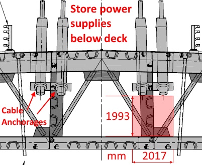
Store power supplies below deck

Deck Section Stay Cable Anchorage

Deck cable anchor
DC Circuit Diagrams
Locating all the electrics at the deck anchorages, while leaving the strands earthed at the tower anchorages, offers advantages for design, development, installation, commissioning and servicing.


Heating strands pair voltage balance detector
The window detector circuit compares the isolated power supply’s potential with respect to earth to detect the expected balance of resistance and voltage in the heating strands pair. If an imbalance fault develops then the safety switch is used to cut the power.
DC Summary
So isolating the strands for DC heating purposes presents technical challenges. It would be very convenient if the outer strands could be preferentially used for heating purposes without having to isolate the strands electrically etc. but to achieve that we must consider using not direct current but alternating current instead.
Alternating Current Heating
The skin effect observed with alternating current changes matters in that with increasing frequency the heating current will tend to distribute towards strands nearer the surface of a cable. However if too great a frequency is used then the skin effect will increase the resistance of even the most superficial strands so much that inappropriately high and difficult to insulate against voltages would be required to obtain the required heating power.
Assuming that the appropriate AC frequency can be determined for preferentially heating the superficial strands of the Queensferry Crossing stay cables, although there would be no need to isolate the strands from the anchor head, there then presents the challenge of isolating the anchor heads and anchorages so that the current is not dissipated through the bridge instead of heating the cables as required.
Having isolated the cables for heating purposes, one may then wish later to reconnect the cables electrically to the rest of the bridge and disconnect the heating power supplies for lightning protection purposes. Certainly, one would not wish to encourage a lightning strike to find its way to ground via the bridge’s cable deicing power supplies!
Tower ice
To prevent the bridge piers or towers (with non-conducting concrete surfaces) from icing up, they could have been surface fitted with new electrical heating trace cables which are then appropriately electrically-powered for deicing when necessary.
Ideally, such additional heating elements would have been embedded into the surface of the piers at construction time. Too late for that now.
Another option to consider is heating the hollow towers from within. However, considering the considerable mass and thickness of the towers, their surfaces would have to be kept above freezing temperature all winter long. Heating the towers from within, there simply wouldn’t be time to allow the towers to get freezing cold because there was no icing then suddenly heat them from the inside to deice a sudden incidence of icing.
So heating from within bridge towers would use more electricity, though the cost shouldn’t be prohibitive – surplus grid electricity is a common occurrence at times of high wind power generation, so the electricity grid managers should offer a very low price for such electricity (just the grid connection charge) – plus it should be a lot safer upgrade from the point of view of bridge users – far less chance of things falling onto the road during the fitting of the towers’ internal heating elements.
Heating the towers may be as simple as a big electric heater on the ground floor, the warm air rising up the insides of the towers, in between the open stairways and scaffolding.
Laboratory Tests
Scotsman: Lab tests for measures to stop ice falling from Queensferry Crossing
“Technology to prevent ice falling from the Queensferry Crossing is to be tested in a specially-created laboratory that will replicate the climactic conditions required for ice to form on the bridge.”
Transport Scotland is already mismanaging this useful new test lab by refusing to use the cable strands as “heated wires”, as I propose.
The Scottish Government should commission me to de-ice the Queensferry Crossing and to manage this lab, ending Transport Scotland’s mismanagement.
“Cable sheath surface modifications” [WRONG] – mesh offers additional surfaces for ice to form on and fall from
“mechanical vibration / ultrasonic” [WRONG] – limited range so would destroy near plastic stay pipe before dislodging distant ice
“robotics” [WRONG] – unreliable / maintenance issues
Trace heating is a low-maintenance industry standard.
Using the bridge’s own cable strands to carry the trace current is innovative but equally low maintenance.
So Transport Scotland mislead by claiming “significant maintenance challenges” for heated wires.
Cunning Diversion Plan

Transport Scotland’s cunning plan to divert traffic when the Queensferry Crossing has to close for ice
Tel.01224 583906 (landline, goes straight to answering machine)